
Basic Motor Driver

The Basic Motor Driver shield is a motor driver for two brush DC motors or one bipolar stepper motor. Rated for 30V and 2A peak current operation, the Basic Motor Driver is one of the lowest-cost medium-power motor driver solutions available for Arduino. The shield is directly compatible with the Ruggeduino, Arduino Uno, Duemilanove, and Mega, or can be used as a standalone motor driver with any microcontroller board. The Basic Motor Driver is also easy to embed into robot platforms or multi-axis motor control systems.
Please visit the Product page for purchasing information.
We also offer the more powerful and more rugged Rugged Motor Driver -- see this application note if you need guidance on choosing the right motor driver for your project.
Features
- Operation from 8V-30V and 2A peak per phase
This is one of the lowest-cost medium-power motor drivers available.
- Reverse voltage protection
Hook up the power supply backwards with most motor drivers and you can throw them in the trash. Not so with the Basic Motor Driver. It is fully reverse voltage protected up to 40V.
- Simple enable/direction interface
Each motor (or stepper motor phase) is controlled by only 2 inputs: ENABLE and DIRECTION. The ENABLE input can be driven by a PWM output to control the average motor current. The DIRECTION input controls the direction of current flow. These four digital pins completely control 2 brush DC motors or 1 bipolar stepper motor. This interface is compatible with other popular Arduino motor driver shields. See the Connections section below for how to hook up these signals.
- Use external power or Arduino power
You can either use an external voltage source (8V-30V) or use the Vin power from the Arduino. NOTE: For external voltages greater than 15V you must cut jumper J17 when the shield is plugged in to an Arduino (the Ruggeduino is OK up to 24V). See the diagram below in the Connections section for the location of this jumper.
- Terminal blocks included and assembled
The L298P motor driver, 2-pin 3.5mm terminal blocks, protection diodes and resistors, etc. are all pre-assembled to the board. To use as an Arduino shield, you will need to purchase and solder either pin headers or stacking headers. You will need two 6-pin headers and two 8-pin headers. To use as a standalone motor driver, either solder wires directly to the board or solder in a 6-pin terminal block.
- Configurable control pins for driving multiple motors
Within a few minutes you can modify the Basic Motor Driver to use different control pins (simple soldering required). Together with stacking headers this means you can stack multiple Basic Motor Driver shields together and independently control multiple motors. Since the Arduino has 6 PWM outputs you can stack up to 3 shields together and independently have PWM control over 6 DC motors or 3 stepper motors. More info below.
- Parallel phases for double the current
For driving one DC motor you can connect the two output phases in parallel and get twice the current output. See our application note for more details.
Sample Sketches
Here are some sample programs for demonstrating the applications of the Basic Motor Driver. They are provided as INO files (i.e., sketches) for use with the Arduino development environment.
- Basic DC Motor Control: INO file: rmcbasic.ino
This sketch demonstrates how simple it is to use the Basic Motor Driver to control the direction and rotation of two brush DC motors.
- Stepper Motor Control: INO file: stepperdemo.ino
This sketch demonstrates keyboard control of a stepper motor. Open up the serial monitor (or any other terminal program) and use single-keystroke commands to control stepper motor speed, direction, and power. See the documentation in the sketch for usage notes.
The sketches above make use of the built-in Stepper library that comes with the Arduino software. The AccelStepper library is another library for controlling stepper motors and has more features and more examples.
NOTE: The AF_Motor library is only designed to work with the Adafruit motor shield and will not work with the Basic Motor Driver or other motor drivers that directly control motor driver pins.
Connections
Basic Control
The following Arduino pins are used by default to control the two motor outputs.
| Pin | Function |
|---|---|
| D3 | ENABLE1 |
| D12 | DIRECTION1 |
| D11 | ENABLE2 |
| D13 | DIRECTION2 |
The pin assignments can also be changed with some simple board modifications.
ENABLE1 and ENABLE2 can be driven with steady logic level signals (high to enable motor power, low to disable it) or driven by PWM outputs to vary the average motor current smoothly from no power to full power.
The DIRECTION1 and DIRECTION2 signals control the direction of the flow of current in each motor output, hence the direction of rotation for brush DC motors.
For stepper motors, these two direction outputs must be pulsed in the proper sequence to effect forward or reverse rotation. The Stepper library handles this logic for you.
Power In / Motor Out
Terminal block J1 provides an optional 8V-30V external power input connection. The VIN external voltage input to the Arduino can also be used to power the motors instead of applying power at J1.
The motor outputs are available at terminal blocks J2 and J3.
- A bipolar stepper motor is driven by connecting each one of its coils to these two terminal blocks.
- Two brush DC motors can be driven by connecting each motor to one to these two terminal blocks.
- A single brush DC motor can be driven at twice the current by paralleling the outputs of the two terminal blocks. See this application note for more details.
Note that by default, the power input at J1 and the VIN external voltage input are connected (separated by a diode so that the VIN external voltage input cannot be observed at J1 -- see the schematic). This means that when external power inputs greater than 15V are to be used, jumper J17 must be cut else damage to the Arduino can result since it was only designed for VIN voltages of 15V or less. When using the Ruggeduino, input voltages may be as high as 24V before J17 must be cut. See the diagram below for the position of jumper J17.

If jumper J17 is left connected then the voltage applied at terminal block J1 can power both the motors and the Arduino.
Power provided through terminal block J1 is reverse voltage protected at up to 40V. If you reverse the polarity of the wires at this connector (i.e., you apply up to -40V), the motor driver will not be damaged.
The L298P motor driver tolerates positive input voltages of up to 46V, but we suggest limiting the applied voltage to 30V. When switching large inductive loads, like motors, back-emf voltages greater than the applied voltages can result, especially when quickly reversing the direction of current in a coil (for example, stepping a stepper motor). Rather than quoting the absolute maximum voltage of 46V from the L298P datasheet, we believe it is more prudent to apply a maximum voltage (30V) in normal operation.
Rewiring Control Inputs
If you want to use pins other than D3/D11/D12/D13 to control your motors you can do so with some simple board modifications. You will need:
- hobby knife / craft knife : these are available for $2-$3 at just about any craft store or hardware store
- soldering iron
- solder
- hookup wire
Here is the procedure for rewiring the control inputs:
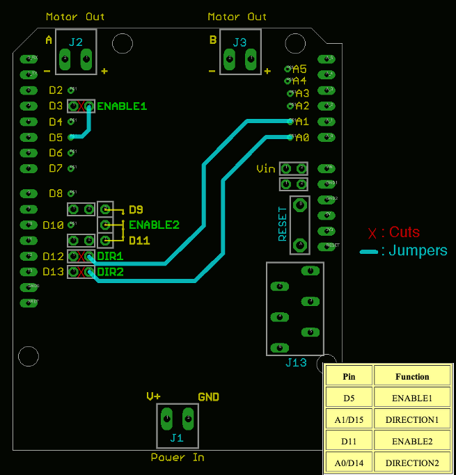
- Use the hobby knife to cut the connection for the control pin you want to disconnect (one of D3/D11/D12/D13). See the layout diagram above for the jumper locations, or the diagram below for an example.
- Solder in one end of a wire to the jumper pad that you want connected to an Arduino pin.
- Solder in the other end of the wire to the desired control input jumper pad.
For example, here is a diagram of a Basic Motor Driver rewired to the control scheme shown in the table below. Notice that D5 is a PWM-capable output, thus is an appropriate choices for the ENABLE1 control input.
Standalone Motor Driver
The Basic Motor Driver can be used as a standalone motor driver (without an Arduino) by providing an 8V-30V DC voltage at terminal block J1 and wiring control signals to connector J13. Note that connector J13 is not populated -- you can solder wires directly to the pads on the board or you can purchase our 6-pin quick-connect terminal block that can be soldered in for J13.
As an alternative, you can also purchase a Quick Shield or Aussie Shield and make connections to the Basic Motor Driver using quick-connect terminals -- no soldering required.
The connections for J13 are shown in the table below.
| Pin | Function |
|---|---|
| EN1 | Enable (PWM) pin for Motor 1 |
| DIR1 | Direction pin for Motor 1 |
| 5V | Provide a 5V DC supply for powering the L298P. This 5VDC supply must be able to provide at least 40mA. |
| EN2 | Enable (PWM) pin for Motor 2 |
| DIR2 | Direction pin for Motor 2 |
| GND | 0V reference -- must be the same as 0V reference for power provided at terminal block J1. |
chipKIT Compatibility
The Basic Motor Driver is easily compatible with the Microchip chipKIT Uno32 and Max32 boards. You must, however, rewire the ENABLE2 control input to use D9 instead of D11, since D11 is not a PWM output on the chipKIT. This is easy to accomplish using connector J4 (see above). By default, J4 connects D11 to the ENABLE2 signal. You can cut this connection on the bottom side of the board using a hobby knife, and short the connection from D9 to ENABLE2 using a 2-pin 0.1” pin header and shunt.
Uncooled Power Handling
With no forced air flow or other active cooling mechanism, no motor driver integrated circuit is going to achieve its maximum rated current. See our application note The Motor Driver Myth for an explanation of why heat is the limiting factor in how much current you will actually be able to deliver to your motors.
Although the L298P devices are rated for 2A of peak current in each motor channel, this current cannot be sustained unless there is forced air flow or other active cooling. The same problem exists, and can even be worse, for other motor drivers based on the L298P, depending on how well the printed circuit board is designed to manage the heat. In our laboratory tests, the Basic Motor Driver can sustain 2A of current in one motor output (with the other motor output completely off) or 1A in both motor outputs simultaneously (at room temperature).
Accessories
The Basic Motor Driver comes assembled as shown:

Additional accessories available for purchase are:
- 8-pin and 6-pin pin headers: these allow the Basic Motor Driver to plug in to an Arduino (or compatible board)
- 8-pin and 6-pin stacking headers: these allow the Basic Motor Driver to plug in to an Arduino (or compatible board) and also allow additional shields to stack on top
- 6-pin spring terminal block: solders in to connector J13 to allow for easy standalone operation
- 2-pin pin headers: not required but can be soldered in to positions J5, J6, J7, J11, J12 or J17 if those jumpers were previously cut
- 2-pin shunts: used for shorting out the 2-pin pin headers
Technical Data
- Here is the schematic of the Basic Motor Driver.
- Here is the datasheet of the L298P 2A H-bridge driver
The Basic Motor Driver was designed in the USA and is assembled in the USA using lead-free components and lead-free manufacturing and assembly processes.